Hydraulic systems depend on power, but their longevity relies on precise control. Insufficient pressure results in poor performance, while excessive pressure causes detrimental heat, wear, leaks, and component failure. Pressure reducing manifolds are essential for achieving this balance, ensuring a circuit receives the exact necessary pressure… and no more.
Pressure reducing manifolds aren’t just components added for compliance or convenience. They are system-level solutions that protect sensitive circuits, improve efficiency, and extend the life of hydraulic equipment across mobile and industrial applications. When designed and applied correctly, they quietly solve problems operators never have to think about. When they’re misunderstood or misapplied, the consequences show up fast.
This guide explains what pressure reducing manifolds are, how they work, where they’re used, and why they’re often the smarter alternative to individual valves or improvised pressure control solutions.
What Is a Pressure Reducing Manifold?
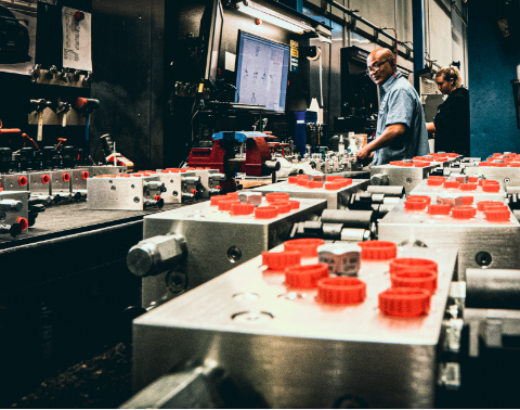
A pressure reducing manifold is a hydraulic manifold assembly that incorporates one or more pressure reducing valves to supply a downstream circuit with a controlled, lower pressure than the main system pressure.
In simple terms, it allows a single hydraulic system to safely operate multiple circuits that require different pressure levels.
Unlike a standalone pressure reducing valve installed inline, a manifold integrates the pressure reducing function into a compact, engineered block that may also include relief valves, check valves, flow controls, or directional valves. This integration improves reliability, reduces leak points, and simplifies system layout.
Key characteristics of pressure reducing manifolds:
- Maintain a constant reduced pressure in a specific circuit
- Isolate sensitive components from high system pressure
- Operate independently of upstream pressure fluctuations
- Compact, integrated, and application-specific
These manifolds are commonly used when a system must deliver high pressure for one function while protecting lower-pressure actuators, controls, or auxiliary devices elsewhere.
How Pressure Reducing Manifolds Work
A pressure reducing manifold works by controlling pressure after the valve, not before it.
When hydraulic fluid enters the manifold from the main pressure supply, the internal pressure reducing valve monitors downstream pressure. If that pressure rises above the preset value, the valve throttles flow or diverts excess pressure to maintain the desired reduced level.
This allows the downstream circuit to operate at a safe, consistent pressure even if upstream pressure fluctuates due to load changes or system demand.
Importantly, pressure reducing valves are normally open. That means fluid flows freely until the reduced pressure setpoint is reached. Once it is, the valve actively regulates to prevent pressure from climbing higher.
In a manifold configuration, this function becomes more stable and predictable because:
- Internal flow paths are optimized
- Pressure signals are cleaner and less affected by plumbing losses
- Supporting components can be integrated for better control
The result is smoother operation, less heat generation, and improved protection for downstream components.
Pressure Reducing Manifold vs Pressure Relief Manifold
One of the most common sources of confusion in hydraulic design is the difference between pressure reducing and pressure relief functions.
A pressure relief manifold protects the entire system by limiting maximum pressure. It reacts only when pressure exceeds a set limit and dumps excess fluid to tank.
A pressure reducing manifold protects a specific circuit by maintaining a lower pressure than the rest of the system, continuously, not just during overpressure events.
They serve different purposes and are not interchangeable.
Pressure reducing manifolds:
- Control pressure downstream
- Enable multiple pressure zones
- Improve efficiency in sensitive circuits
Pressure relief manifolds:
- Limit maximum system pressure
- Provide safety protection
- Do not regulate downstream pressure levels
Using a relief valve where a reducing valve is required often leads to unstable pressure, excessive heat, and inconsistent actuator behavior.
Why Use a Pressure Reducing Manifold Instead of Individual Valves?
While it’s possible to assemble pressure reducing functions using individual inline components, manifolds offer several practical advantages.
First, manifolds significantly reduce plumbing complexity. Fewer hoses and fittings mean fewer leak points, less pressure drop, and improved reliability.
Second, integrated manifolds improve performance consistency. Internal flow paths are engineered for predictable behavior, reducing pressure oscillation and response delays that can occur with scattered components.
Third, manifolds simplify maintenance and troubleshooting. When pressure control elements are consolidated into a single assembly, diagnosing issues becomes faster and more accurate.
Additional benefits include:
- Space and weight savings (critical in mobile equipment)
- Improved contamination control
- Cleaner system layout
- Easier system replication and scaling
For OEMs and system designers, manifolds also improve repeatability across machines and reduce variability in field performance.
Common Applications for Pressure Reducing Manifolds
Pressure reducing manifolds are used anywhere a hydraulic system must support multiple pressure requirements without sacrificing safety or efficiency.
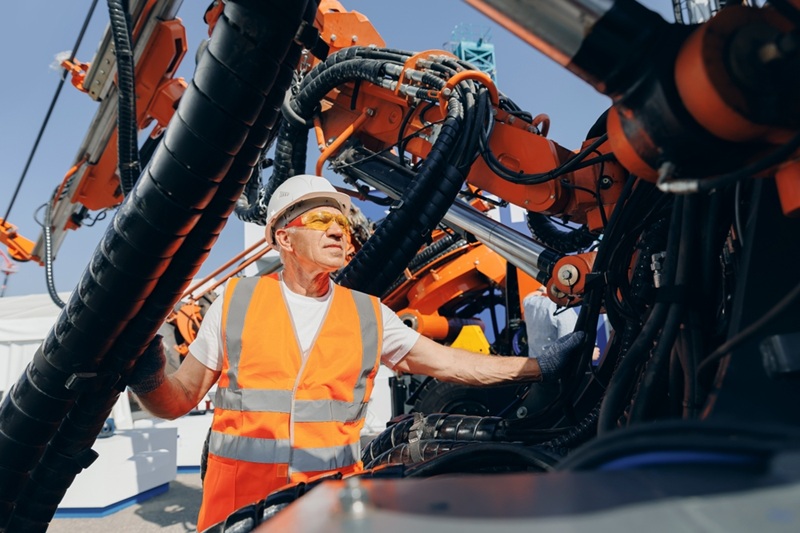
Mobile Equipment
In construction, agricultural, and material handling equipment, pressure reducing manifolds protect auxiliary functions such as steering, braking, cab controls, and tool circuits. These functions often require lower pressure than the main working hydraulics but must remain responsive and reliable.
Industrial Machinery
Machine tools, presses, and automation systems rely on pressure reducing manifolds to maintain precise force control. Sensitive clamping, positioning, or actuation functions benefit from stable pressure independent of main system demand.
Specialized Systems
Test stands, multi-pressure power units, and systems with proportional or electro-hydraulic controls frequently use pressure reducing manifolds to isolate critical components and ensure consistent performance.
In each case, the goal is the same: deliver the pressure that function needs. No more, no less.
Key Design Considerations
Selecting or designing a pressure reducing manifold requires more than matching pressure ratings.
Critical considerations include:
- Required reduced pressure range and accuracy
- Maximum and continuous flow rates
- Response time under dynamic loads
- Heat generation from throttling
- Contamination sensitivity
- Interaction with upstream pressure changes
- Safety margins for pressure spikes
Ignoring these factors can result in unstable control, excessive heat, or shortened component life. This is why pressure reducing manifolds are often engineered as part of a complete system rather than added later as a fix.
Integrated Manifolds and Custom Solutions
In many real-world applications, pressure reduction is only one part of the solution.
Custom manifolds often integrate pressure reducing valves with:
- Relief protection
- Load-holding valves
- Directional control
- Flow regulation
- Check valves
By combining these functions into a single block, system designers reduce complexity while improving performance and safety.
Custom manifolds are especially valuable in space-constrained equipment, high-duty-cycle systems, and applications where reliability is critical.
Common Problems Caused by Improper Pressure Reduction
When pressure reducing is misunderstood or misapplied, issues appear quickly.
Common problems include:
- Premature seal and hose failure
- Unstable actuator movement
- Excessive heat generation
- Energy loss and inefficiency
- Increased downtime and maintenance costs
In many cases, these problems are not caused by faulty components, but by incorrect pressure control strategy.
How to Select the Right Pressure Reducing Manifold
 Choosing the right pressure reducing manifold starts with understanding the system, not the catalog.
Key questions include:
- Which circuits require reduced pressure?
- How stable must that pressure be?
- What happens during load changes?
- How does temperature affect performance?
- Is future system expansion likely?
Our pressure-reducing vendors include Sun Hydraulics and HydraForce. Working with a hydraulic partner who understands application context ensures pressure control is designed into the system, not added as an afterthought.
Pressure Control Is System Control
Pressure reducing manifolds are vital, yet often overlooked, elements for optimal hydraulic performance. They are essential for protecting components, ensuring stable operation, and boosting efficiency in both mobile and industrial applications.
Properly designed manifolds simplify complex systems and act as a preventive measure, solving potential problems before they lead to system failures.
In hydraulics, managing pressure effectively is not just about power, but system reliability and responsibility.
Pressure Reducing Manifolds: Common Questions
What does a pressure reducing manifold do?
It maintains a lower, controlled pressure in a specific hydraulic circuit while allowing the rest of the system to operate at higher pressure.
Where should a pressure reducing manifold be installed?
It is installed upstream of the circuit requiring reduced pressure, typically close to the protected components.
Can one pressure reducing manifold supply multiple circuits?
Yes, depending on design. Manifolds can include multiple reducing sections for different pressure zones.
Do pressure reducing manifolds generate heat?
They can, due to throttling. Proper sizing and system design minimize heat generation.