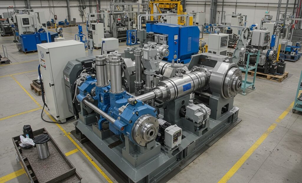
Hydraulic systems are everywhere. In the construction equipment reshaping a job site, the factory press stamping metal parts, the aircraft deploying its landing gear, and the forklift moving pallets across a warehouse floor. They’re one of the most reliable and powerful ways to transmit force, and they’ve been doing it across virtually every industry for well over a century.
But how does a hydraulic system actually work? And what are the individual components that make it function? Whether you’re new to fluid power or just want a clearer picture of how these systems are put together, this guide walks through the essential building blocks of any hydraulic system.
The Basic Principle: Pascal’s Law
Before diving into components, it helps to understand the physics at work. Hydraulic systems operate on Pascal’s Law, which states that pressure applied to a confined fluid is transmitted equally in all directions throughout the fluid.
In practical terms, this means a relatively small force applied to a small area of fluid can generate a very large force at a larger area — which is why a hydraulic cylinder can lift a car, a crane can hoist tons of steel, or a press can stamp thick metal sheets with precision. The fluid itself, typically hydraulic oil, is the medium through which that force is transmitted.
With that foundation in place, here are the core components that make it all work.
1. Hydraulic Reservoir (Tank)
The reservoir is where the hydraulic fluid is stored when it’s not actively circulating through the system. It’s the starting and ending point for the fluid in every cycle.
But the reservoir does more than just hold fluid. It also:
- Allows heat to dissipate from returning fluid
- Gives entrained air a chance to separate out of the fluid
- Provides a settling zone where contaminants can sink out of circulation
- Acts as an expansion chamber to accommodate fluid volume changes
Reservoirs are typically made from steel or aluminum and are sized based on the system’s flow rate and thermal requirements. Proper reservoir design is an underappreciated factor in system longevity. An undersized or poorly designed tank leads to overheating and contamination problems that degrade every other component downstream.
2. Hydraulic Pump
The pump is the heart of the hydraulic system. Its job is to move fluid from the reservoir into the system under pressure, converting mechanical energy (from an electric motor or engine) into hydraulic flow.
It’s worth noting what a hydraulic pump actually does and doesn’t do: a pump creates flow, not pressure. Pressure is a result of resistance to that flow. The pump pushes fluid through the system; the load and the valves determine how much pressure builds up.
Common pump types include:
- Gear pumps: Simple, cost-effective, and robust. Widely used in mobile and industrial applications where moderate pressure is sufficient.
- Vane pumps: Quieter than gear pumps and capable of more consistent flow. Common in industrial machinery.
- Piston pumps: The highest-performing option — capable of handling high pressures and variable flow rates. Used in demanding applications like aerospace, heavy construction, and precision manufacturing.
Pump selection depends on the required flow rate, operating pressure, efficiency requirements, and duty cycle of the application.
3. Hydraulic Valves
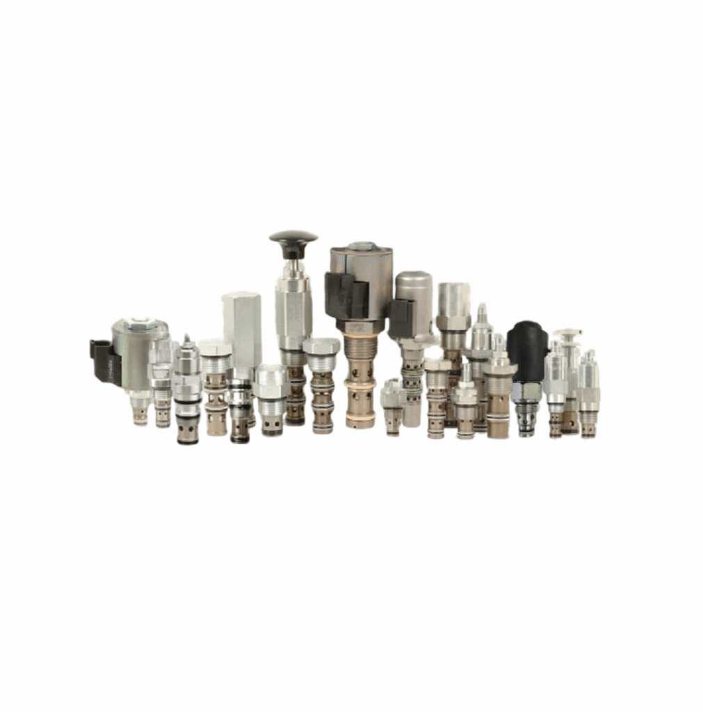
Valves are the control elements of the system. They regulate where fluid goes, how much of it flows, and at what pressure, giving operators and automated systems precise control over every function the hydraulic system performs.
There are three primary categories of hydraulic valves:
Directional Control Valves – These determine which path the fluid takes through the circuit — routing it to extend or retract a cylinder, rotate a motor clockwise or counterclockwise, or hold a load in position. They’re the valves that most directly control the motion of hydraulic actuators.
Pressure Control Valves – These protect the system and control the force output of actuators. Relief valves set the maximum system pressure to prevent damage. Pressure-reducing valves limit pressure in specific branches of the circuit. Sequence valves ensure operations happen in the correct order.
Flow Control Valves – These regulate the speed of actuators by controlling how much fluid flows to them per unit of time. Controlling flow rate controls actuator velocity, which is how hydraulic systems achieve precise, repeatable motion speeds.
In many modern systems, these individual valve functions are integrated into a single manifold block, reducing external plumbing, minimizing leak points, and simplifying the overall system layout.
4. Hydraulic Actuators
If the pump is the heart of a hydraulic system, the actuators are its muscles. Actuators are the output devices that convert hydraulic pressure and flow back into mechanical force and motion.
There are two main types:
Hydraulic Cylinders (Linear Actuators) – Cylinders convert fluid pressure into straight-line (linear) force and movement. A piston inside a cylinder bore moves in or out as fluid is directed to one side or the other. Cylinders are used everywhere — from the boom and bucket of an excavator to the clamping jaws of a press to the steering on heavy trucks.
Hydraulic Motors (Rotary Actuators) – Motors convert fluid flow into rotational motion. They’re used wherever continuous rotation is needed — conveyor drives, winches, wheel drives on mobile equipment, and drill heads, among many others.
Actuator sizing is based on the force or torque required, the stroke or rotation needed, and the available system pressure.
5. Hydraulic Fluid
Hydraulic fluid is the medium that makes the whole system work — transmitting power, lubricating internal components, carrying away heat, and protecting against corrosion and wear.
Most hydraulic systems use petroleum-based hydraulic oil, but the right fluid choice depends on the application. Fire-resistant fluids are used where there’s a risk of ignition (steel mills, die casting, aviation). Biodegradable fluids are used in environmentally sensitive applications like forestry or marine equipment. Water glycol fluids offer fire resistance at a lower cost than synthetics.
Fluid cleanliness is critical. Contaminated fluid — whether with particles, water, or air — is the leading cause of hydraulic component failure. Maintaining proper filtration and adhering to fluid change intervals is one of the most important things you can do to protect a hydraulic system.
6. Filters
Filters remove contaminants from the hydraulic fluid before they can damage pumps, valves, and actuators. They’re typically positioned at key points in the circuit: at the pump inlet (suction filter), in the pressure line, and in the return line as fluid flows back to the reservoir.
Filter ratings are expressed in microns. The smaller the micron rating, the finer the filtration. Tighter filtration protects more sensitive components (like high-performance piston pumps and servo valves) but requires more frequent maintenance.
7. Hydraulic Hoses, Tubing, and Fittings
These are the pathways that connect every other component in the system. Hoses, tubes, and fittings must be sized and rated to handle the system’s flow rate and pressure, including pressure spikes.
Poor plumbing is a common source of system problems: undersized lines create excessive pressure drop and heat; improper fittings leak; and hoses routed near heat sources or sharp edges wear prematurely. In many modern systems, hard-plumbed external connections are replaced by integrated manifold blocks, which route fluid internally and eliminate most external connections entirely.
8. Heat Exchangers (Coolers)
Hydraulic systems generate heat from fluid friction, pressure drops across valves, and the inefficiencies inherent in any mechanical system. If that heat isn’t managed, fluid degrades faster, seals fail sooner, and component life shortens across the board.
Heat exchangers (also called hydraulic coolers) transfer heat from the hydraulic fluid to either air or water. Air-blast coolers are common on mobile equipment; water-cooled heat exchangers are often used in stationary industrial applications where cooling water is available.
How It All Works Together
A complete hydraulic system cycle looks like this: the pump draws fluid from the reservoir and sends it under pressure through the system. Valves direct that pressurized fluid to the appropriate actuator — a cylinder or motor — which converts the hydraulic energy into useful mechanical work. After doing its work, the fluid returns to the reservoir through the return line, passing through a filter along the way, where it cools, settles, and is ready to be circulated again.
Every component in that loop plays a specific role, and the performance of the system as a whole is only as good as its weakest link — which is why quality component selection, proper system design, and regular maintenance all matter.
Working with a Hydraulic Systems Expert
Understanding the components is the first step. Designing a system, or troubleshooting one that isn’t performing, requires deep application knowledge and access to quality components.
Hydra-Power Systems has been supplying and designing hydraulic and pneumatic systems since 1970. From individual components to complete custom manifold assemblies and hydraulic power units, our team helps engineers and operations managers across industries get the right solution for their specific application.