
Variable displacement piston pumps occupy a critical position in mobile hydraulic system design. They are the energy source that makes everything else on the machine work. And unlike fixed-displacement gear pumps, they adjust their output to match what the system actually needs in real time.
For OEMs designing equipment where efficiency, power density, and controllability matter, the pump selection decision has downstream consequences for nearly every other component in the hydraulic circuit.
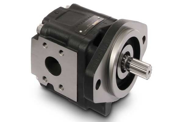
Casappa’s MVP series variable displacement axial piston pumps have earned a strong reputation in the mobile hydraulics market for combining proven swash plate technology with a compact envelope, a broad range of control options, and the through-drive flexibility that makes them practical for both single-pump and tandem configurations. They are built for the medium to high-pressure demands of mobile work machinery: excavators, telehandlers, loader cranes, utility vehicles, forestry equipment, and the broader category of machines where hydraulics do the work.
Hydra-Power Systems stocks Casappa MVP pumps in four displacement sizes at our Portland, Oregon facility and offers a pump build and configuration program that supports everything from rapid prototype builds to production-ready configured assemblies. For OEM engineering teams in the Pacific Northwest — and customers shipping nationwide — this means the combination of a quality European-engineered pump and a local technical resource that can put the right configuration in your hands quickly.
This post covers the MVP series in depth: how the technology works, what the key specifications mean in practice, how the available controls match to common mobile applications, and how Hydra-Power Systems’ Portland Build Center supports customers from initial specification through production.
What Makes Variable Displacement Piston Pumps the Right Choice for Demanding Mobile Applications
Before diving into the MVP specifically, it’s worth establishing why variable displacement piston pumps occupy the top of the performance pyramid in mobile hydraulic system design — and when that premium over simpler pump technologies is justified.
Fixed vs. Variable Displacement: The Efficiency Argument
A fixed-displacement pump delivers the same volume of fluid per revolution regardless of what the system demands at any given moment. When the machine is idle, when an actuator is holding position, or when the system is operating at partial load, a fixed-displacement pump continues moving fluid at full theoretical delivery. That fluid has to go somewhere — typically over a relief valve or through an open-center directional valve — and the energy spent pumping that fluid converts directly to heat. In high-duty-cycle mobile applications, this wasted energy is significant: it loads the engine, increases fuel consumption, degrades hydraulic fluid faster, and creates thermal management challenges.
A variable displacement pump solves this by continuously adjusting its displacement — the volume delivered per revolution — to match what the system actually demands. When demand is low, displacement decreases and the pump consumes less power. When the system calls for full flow at high pressure, displacement increases to meet it. The mechanical mechanism that accomplishes this in the MVP series is a tilting swash plate: the angle of the swash plate relative to the rotating cylinder barrel determines the stroke length of the pistons, which determines the displacement per revolution. Electronic or hydraulic control systems vary this angle in response to system signals.
For mobile equipment running work cycles that alternate between high-demand functions and idle or partial-load periods — which describes virtually every excavator, telehandler, crane, harvester, and work truck in operation — variable displacement directly reduces fuel consumption, reduces heat generation, and extends system component life.
Why Piston Over Vane or Gear for Medium to High-Pressure Mobile Work

Within the category of variable displacement pumps, axial piston pumps outperform vane pumps and gear pumps in the pressure and power density ranges that define modern mobile hydraulic systems. Key advantages include:
Piston pumps operate reliably at continuous pressures of 280 bar (4,060 psi) and peak pressures reaching 350 bar (5,075 psi) — pressure levels that exceed the practical limits of most vane pump designs and far exceed what gear pumps handle comfortably. Modern mobile equipment consistently operates at system pressures of 200–280 bar continuous, making piston pumps the appropriate technology for these systems.
Volumetric efficiency — the ratio of actual flow delivered to theoretical displacement — is higher in piston pumps than in gear or vane designs at elevated operating pressures. This means piston pumps lose less flow to internal leakage under load, delivering more of their rated displacement to the system and maintaining flow accuracy as system pressure increases.
The control flexibility available on axial piston pumps — pressure compensation, load sensing, torque limiting, electrohydraulic control — is substantially greater than what’s achievable on fixed or variable vane designs. For mobile machine architects building electronically managed systems, this control flexibility is often decisive.
The Casappa MVP Series: Technical Overview
Casappa S.p.A. is an Italian manufacturer with decades of specialized focus on hydraulic pumps, motors, and filters. The MVP (Mobile Variable Pump) series reflects that focused development: it’s an axial piston variable displacement pump designed specifically for open circuit mobile hydraulic applications, with a form factor and feature set optimized for direct engine mount configurations and the demanding duty cycles of work machinery.
Operating Principle: Swash Plate Axial Piston Design
The MVP uses a swash plate design in which a rotating cylinder barrel houses nine pistons arranged axially around the shaft centerline. As the barrel rotates, the pistons ride against the inclined swash plate, causing them to reciprocate within their bores. The inlet and outlet ports are separated by a valve plate, so each piston draws fluid in during the extension stroke and expels it during the compression stroke.
The displacement — and therefore flow rate at a given shaft speed — is controlled by changing the angle of the swash plate. At zero angle, piston stroke is zero and displacement is zero. At maximum angle, stroke is maximum and flow is at full rated displacement. The control mechanism that sets this angle is one of several options described below.
This design produces smooth, low-pulsation flow compared to lower-cylinder-count pump designs, which contributes to reduced noise and reduced pressure fluctuation at the system level. Nine pistons mean nine delivery pulses per revolution, which are inherently smoother to filter and dampen than the three or four pulses from a gear pump of equivalent displacement.
Key Specifications
The MVP series as stocked and supported by Hydra-Power Systems covers the following core specifications:
Displacement Range: Hydra-Power Systems stocks the MVP in four displacement sizes — 34cc/rev, 53cc/rev, 84cc/rev, and 100cc/rev — covering the mid-to-large displacement range most relevant to construction, forestry, agricultural, and material handling equipment with moderate to high flow demands.
Pressure Ratings: Continuous operating pressure is rated at 280 bar (4,060 psi). Intermittent pressure — the rating applicable to transient conditions such as load impacts and relief valve cracking — reaches 315 bar (4,568 psi). Peak pressure rating is 350 bar (5,075 psi), covering worst-case transients in demanding applications. These pressure ratings are appropriate for the majority of mobile machine hydraulic systems currently in production.
Speed Range: Maximum shaft speed reaches 3,500 RPM at minimum displacement settings, with the specific maximum speed varying by displacement size and inlet conditions. At full displacement and standard inlet conditions, speeds up to approximately 2,500 RPM are typical operating points on direct engine drive applications. The MVP accommodates the speed ranges of diesel and gasoline engines across the typical 1,000–2,500 RPM operating band for mobile work equipment.
Flow Output: At 34cc/rev and 1,500 RPM, peak theoretical flow is approximately 51 LPM (13.5 GPM). At 100cc/rev and 1,500 RPM, peak theoretical flow reaches approximately 150 LPM (39.6 GPM). Actual delivered flow is reduced slightly by volumetric efficiency, which is high in piston pump designs — typically 95–98% at normal operating conditions.
Fluid Requirements: The MVP is designed for standard hydraulic mineral oils with viscosity in the range of 15–100 cSt operating viscosity, with optimal performance in the 25–46 cSt range. Case drain temperature should not exceed 90°C (194°F) continuous.
Rotation: All HPS-stocked MVP inventory is clockwise rotation (viewed from the shaft end). Hydra-Power Systems can change the valve plate to convert to counterclockwise rotation — an important capability for applications where the pump drive configuration requires reverse rotation, without needing to special-order a separate pump model.
Shaft Configurations
The MVP is available with spline shafts and SAE B and SAE C flange mount and shaft configurations, matching the standard mounting interfaces used across the mobile equipment industry. SAE B is the predominant standard for mid-displacement pumps in the 34–53cc range, while SAE C covers larger displacement pumps including the 84cc and 100cc sizes. Spline shaft options accommodate direct coupling to PTO output shafts and pump drive gearboxes. Hydra-Power Systems stocks multiple shaft configurations to support rapid prototype and production builds without extended lead time on special configurations.
Through Drive Capability
The MVP supports through drive configurations — where the rear of the pump provides a shaft output for driving a second pump or hydraulic motor. This is particularly valuable in mobile systems that require multiple pump functions: a typical installation might use a large MVP as the primary implement pump while taking a through drive to a smaller gear pump serving the steering system, brake cooling circuit, or auxiliary function. Through drive eliminates the need for a separate tandem pump adapter or pump drive assembly, simplifying installation and reducing the number of potential leak points.
Control Options: Matching the Pump to the System Architecture
The MVP series’ control flexibility is one of its most significant engineering advantages. Different mobile machine architectures call for different pump control strategies, and the MVP accommodates a range of approaches within the same pump family.
Pressure Compensator (RP Control)
The pressure compensator is the foundational control for variable displacement piston pumps. It operates on a simple principle: the control mechanism continuously senses system pressure and strokes the pump down (reduces displacement) whenever pressure reaches the set point. When the pressure compensator is at its setting, the pump provides just enough flow to maintain that pressure — typically a small standby flow to cover leakage and maintain pressure readiness — while consuming minimal power.
Pressure compensator control is appropriate for systems where the hydraulic functions are controlled by metering valves downstream of the pump, and where the pump’s role is to maintain system pressure at a defined maximum. This is a standard approach for many mobile work functions where the operator controls actuator speed through joystick-operated directional control valve sections and the pump maintains the available pressure regardless of which functions are active.
Load-Sensing Control (LS Control)
Load-sensing control is the preferred strategy for energy-efficient multi-function mobile systems. In an LS system, the pump receives a pressure signal — the load-sensing signal — that represents the highest load pressure currently active in the system. The pump control maintains a defined differential between the outlet pressure and the LS signal (the LS margin, typically 15–25 bar). This means the pump pressure is always just slightly above the highest load pressure in the system, rather than being held at a fixed maximum setting.
The energy efficiency advantage of load sensing over standard pressure compensation is significant: in a pressure-compensated system, a function operating at 150 bar causes the pump to produce flow at the full 280-bar compensator setting, wasting 130 bar of pressure differential across the metering orifice as heat. In an LS system, the pump produces flow at 165–175 bar (150 bar load plus LS margin), reducing that pressure waste by more than 100 bar. Over a full work cycle, this reduction in throttling losses translates directly to lower fuel consumption and reduced heat generation.
The MVP supports load-sensing configurations with separate LS1 (remote sensing line) and LS2 (internal channel) options to accommodate different hydraulic circuit architectures. For mobile OEMs building electronically controlled multi-function machines, LS control on the MVP integrates naturally with load-sensing directional control valve systems such as HAWE’s PSL CAN series.
Flow and Pressure Compensator (RP + LS Combined)
The combined flow and pressure compensator provides both LS control for normal operation and a pressure limit that prevents the pump from exceeding the maximum system pressure regardless of LS signal status. This is a safety-oriented control configuration that ensures pump outlet pressure stays within design limits even in fault conditions where the LS signal might not reflect actual system state.
Torque Limiter
The torque limiter control modulates pump displacement to prevent the pump from demanding more torque from the prime mover than a defined maximum. This is particularly valuable in mobile equipment where the engine must supply power to both the hydraulic system and the drivetrain simultaneously, and where hydraulic demand spikes could cause engine lug-down or stall.
By setting the torque limiter to a value compatible with the available engine power at the operating speed range, the control ensures the pump operates within the engine’s capability at all times. As system pressure rises, the torque limiter reduces pump displacement proportionally to hold total power consumption constant. This results in a system that responds gracefully to heavy loads rather than bogging the engine.
For OEMs building machines with smaller engines or turbocharged diesels with relatively flat torque curves, the torque limiter is often an important element of the pump control specification.
Electrohydraulic Control (Proportional Solenoid)
Electrohydraulic control of the swash plate enables the machine’s electronic controller to set pump displacement directly via a proportional solenoid command signal. Rather than responding passively to system pressure signals, an electrohydraulically controlled MVP can be commanded to specific displacement levels by the machine controller based on operator input, programmed work cycle logic, or sensor-based system management algorithms.
This control mode is the foundation for sophisticated mobile machine management strategies: variable pump displacement coordinated with variable engine speed, predictive flow matching based on operator intent, energy regeneration management in hybrid systems, and automated work cycle control in precision agricultural and construction applications. As mobile machines increasingly incorporate CAN-bus machine controllers managing both the engine and the hydraulic system as an integrated powertrain, electrohydraulic pump control becomes the logical choice for new OEM designs.
Application Scenarios: Where MVP Pumps Deliver Maximum Value
The MVP series’ displacement range, pressure ratings, and control flexibility make it applicable across a broad range of mobile equipment categories. The following scenarios represent the applications where MVP pump characteristics align most directly with system requirements.
Telehandlers and Rough Terrain Lift Equipment
Telehandlers demand hydraulic systems that provide high force for boom extension and lift, accurate position control during load placement, and simultaneous operation of multiple functions — boom extension, lift cylinder, fork tilt, and outrigger circuits — without one function starving another. Variable displacement with load-sensing control matches these requirements precisely: the pump supplies flow at the pressure demanded by whichever function is active, and the LS margin ensures consistent control response regardless of which combination of functions the operator is using.
The 53cc and 84cc MVP sizes cover the flow range of most telehandler hydraulic systems in the 100–250 horsepower class. Through drive capability supports adding a smaller pump for steering or secondary auxiliary circuits without additional drive hardware.
Loader Cranes and Knuckle Boom Trucks
Loader cranes operate hydraulic systems that must simultaneously manage heavy lift loads at high pressure while providing smooth, precise control for load placement. The pressure compensation characteristic of the MVP — stroking down as system pressure approaches the compensator setting — provides inherent load protection: if the operator commands a function beyond the crane’s rated load, the pump delivers flow at the pressure limit rather than building destructive pressure above the relief valve setting.
The 100cc MVP size is well-suited to the flow demands of larger loader cranes, where simultaneous operation of multiple boom sections and rotation drive requires substantial pump delivery. Torque limiter control on these applications ensures the hydraulic system doesn’t overwhelm the truck’s PTO and engine under peak load conditions.
Agricultural Equipment: Sprayers, Harvesters, and Implements
Precision agricultural equipment increasingly relies on electronically managed hydraulic systems for section control, variable rate application, steering, and implement adjustment. The MVP’s electrohydraulic control option integrates with CAN-bus machine controllers to enable flow management strategies that match pump output to actual demand in real time — reducing fuel consumption across long operating days that might span 12–16 hours of continuous field operation.
The 34cc and 53cc displacement sizes cover the flow requirements of many spray boom hydraulic systems and implement control circuits, while the 84cc and 100cc sizes serve larger harvester and self-propelled applicator platforms with higher total flow demands.
The relatively low noise signature of the nine-piston MVP design is a practical benefit for operator comfort on cab-mounted equipment where the hydraulic pump is close to the operator’s environment.
Construction Equipment: Compact Track Loaders, Mini Excavators, and Utility Machines
Compact construction equipment in the 3–10 ton operating class represents a high-volume market for variable displacement piston pumps. These machines work at high duty cycles, often in confined jobsite conditions where operator fatigue is a real factor and hydraulic system response quality directly affects productivity.
The 34cc and 53cc MVP sizes cover the primary implement pump requirements for compact track loaders and mini excavators in this weight class. For machines with dual-circuit systems — separate implement and travel circuits — through drive capability supports a second pump for travel motor drive, implement priority management, or auxiliary hydraulic circuits for attachments.
Pressure compensator control is the most common configuration for compact construction equipment implement circuits, providing straightforward system design and robust performance across the range of operator inputs.
Marine Deck Equipment and Specialty Applications
Marine deck machinery — winches, cranes, anchor handling equipment, hydraulic steering systems on working vessels — requires pumps that combine high pressure capability with reliable performance in adverse environmental conditions. The MVP’s pressure ratings up to 350 bar peak accommodate the high-force requirements of marine crane and winch applications, while the sealed bearing and seal design handle the moisture exposure common to marine installations.
For marine applications driving winches or capstans where overrunning loads can cause motor overspeed, pairing the MVP with load-sensing control and appropriate overrunning load protection valves in the circuit provides a complete solution for controlled load lowering and emergency stop scenarios.
The Hydra-Power Systems Portland Build Center
The Build Center concept at Hydra-Power Systems’ Portland facility is what distinguishes HPS from a conventional stocking distributor for Casappa MVP pumps. Stocking the pumps is the baseline. The Portland warehouse carries MVP inventory in the 34cc, 53cc, 84cc, and 100cc displacement sizes, available for same-day shipment. The Build Center goes further, providing the people and capabilities to configure, adapt, and integrate those pumps into application-specific assemblies without the lead times associated with factory-configured special orders.
Valve Plate Rotation Changes
All HPS-stocked MVP inventory is clockwise rotation as standard. When an application requires counterclockwise rotation — as is sometimes necessary for PTO configurations, engine reverse-rotation drives, or specific tandem pump arrangements — Hydra-Power Systems can change the valve plate at the Portland facility to convert the pump to counterclockwise rotation. This is a precision operation that requires proper tooling and understanding of the pump’s internal geometry, and doing it in-house eliminates the lead time and cost of ordering a separate rotation variant from the factory.
Through Drive Configuration
HPS configures MVP pumps with through drive adapters and rear connection hardware to create tandem pump assemblies for customers who need multiple pump circuits from a single drive point. Configuration options are matched to the customer’s interface requirements — SAE B or C flanges, specific shaft sizes — and the assembled unit is pressure-tested before shipment.
Shaft and Mounting Adaptation
Customers sometimes need shaft or mounting adaptations to fit the MVP into an existing drive interface that was designed around a different pump. The Portland team works with customers on these adaptation requirements, drawing on in-house machining capability and an understanding of SAE pump interface standards to develop solutions that don’t require full machine redesign.
Rapid Prototype Support
For OEM engineering teams in active product development, the combination of MVP pump inventory and Build Center capability at HPS Portland directly compresses the development timeline. When a prototype machine needs a configured pump assembly in days rather than weeks, the Portland team can pull stock, configure to specification, and ship quickly. This matters most at the prototype and validation stages, where schedule pressure is high and the cost of a delayed test build is measured in engineering team time and program weeks.
Standard production pricing applies to Build Center configurations. There is no premium for the configuration work on standard options. Lead times from stock on standard configurations are as fast as same-day for customers within same-day shipping range of Portland.
Production Run Support
As OEM customers move from prototype to production, the Build Center can support consistent supply of configured pump assemblies to production schedule. Having a regional supplier capable of providing configured assemblies rather than individual components reduces assembly labor at the OEM’s facility and provides a single point of contact for pump specification, inventory management, and quality documentation.
Selecting the Right MVP Configuration: A Practical Framework
For engineering teams working through MVP pump selection for a new application, the following framework covers the primary decision variables:
Displacement Sizing
Displacement selection starts with the flow requirement: what volume of fluid does the system need to deliver to the actuator at the commanded speed, at the operating shaft speed of the pump drive?
The basic relationship is: Flow (LPM) = Displacement (cc/rev) × Speed (RPM) / 1000 × Volumetric Efficiency
For a system requiring 80 LPM peak flow with a pump drive speed of 1,800 RPM and assuming 96% volumetric efficiency: Displacement = 80,000 / (1,800 × 0.96) = approximately 46 cc/rev, pointing to the 53cc MVP as the appropriate size with adequate margin.
Margin is important: sizing a variable displacement pump to its absolute flow limit at peak demand leaves no reserve for simultaneous functions, system leakage compensation, or future capacity additions. Selecting the next size up is generally the right call when the calculation lands near a size boundary.
Control Selection
The control selection follows from the system architecture:
For systems using open-center or closed-center directional control valves with a fixed pump pressure setting: pressure compensator (RP) control is standard.
For systems using load-sensing directional control valves, which includes most modern mobile equipment designed for efficiency: LS control (RP + LS) is the appropriate choice.
For systems where engine power management is a primary design constraint: add torque limiter control.
For systems with machine-level electronic management where pump displacement should be commanded by the machine controller: electrohydraulic control via proportional solenoid.
Many applications combine controls — for example, LS control with torque limiting, or electrohydraulic control with a pressure compensator override. The MVP’s modular control architecture accommodates these combinations.
Shaft and Mount Specification
Confirm the required SAE flange size (B or C) and shaft style (spline, keyed, or smooth) from the pump drive interface specification. If the drive interface is an SAE bell housing from a gear pump or motor manufacturer, the SAE B/C flange standard provides direct compatibility. If the interface is a PTO with a specific spline or shaft diameter, confirm the spline standard (typically SAE or ISO) and tooth count.
Rotation Direction
Confirm pump rotation direction relative to the drive. On direct engine PTO drive, standard clockwise rotation (viewed from shaft end) is typical for SAE standard drives. On drives taken from the opposite end of a gearbox or through a coupling that reverses rotation, counterclockwise may be required. HPS Portland can accommodate this with valve plate conversion from stock.
Through Drive Requirements
If the installation requires driving a second pump from the rear of the MVP, specify the rear connection interface — SAE B or C, shaft size and style — and the required torque rating for the through drive. Confirm that the combined torque demand of both pumps stays within the through drive rating of the MVP at the application’s maximum pressure and speed conditions.
Integration with Hydra-Power Systems’ Broader Capabilities
The MVP pump is the energy source for the hydraulic circuit — but the circuit includes much more. Hydra-Power Systems’ position as both a component distributor and a custom manifold manufacturer means the Portland team can support the full circuit design, not just the pump selection.
For OEM customers developing complete hydraulic systems, HPS offers custom hydraulic manifold manufacturing that integrates the directional control, pressure relief, flow control, and load-holding functions downstream of the MVP pump into precision-machined manifold assemblies. Designing the manifold to work with a specific MVP control configuration — for example, matching a load-sensing manifold circuit to an MVP with LS control — is part of the application engineering work the HPS team provides.
For customers who need a complete hydraulic power unit rather than just the pump, HPS Portland assembles HPU packages that integrate the MVP pump with a motor, reservoir, filtration, cooling, and control valve components into a complete, tested power supply. This is particularly useful for customers adding a dedicated hydraulic power source to a machine that doesn’t have an engine-mounted pump drive, such as battery-electric machines using electric motor-driven pump packages.
The distribution capabilities at HPS Portland extend to the full range of components needed alongside the pump: directional control valves, pressure relief valves, flow controls, hydraulic cylinders, motors, accumulators, filters, and fittings — all available from the Portland warehouse with same-day shipping on stocked items.
For customers in the Southeast, Hydra-Power Systems’ Birmingham, Alabama facility provides equivalent distribution and application engineering support, with the same access to Casappa MVP pump inventory and configuration capability.
Why Source MVP Pumps Through Hydra-Power Systems Portland
The case for Hydra-Power Systems as the supply partner for Casappa MVP pumps in the Pacific Northwest comes down to four factors that matter to OEM engineering and procurement teams:
Inventory depth. Four displacement sizes in stock at the Portland facility means no factory lead time on the configurations covering the majority of mobile hydraulic applications. Same-day availability from Portland reaches customers throughout the Northwest rapidly.
Configuration capability. The Build Center’s ability to change valve plate rotation, configure through drives, and adapt shaft interfaces means customers get the configured pump they need, not just the stock variant that happens to be available. This is the difference between a parts house and an application-capable distributor.
Application engineering support. Pump selection, control specification, and integration planning are technical decisions that benefit from a knowledgeable partner. The HPS Portland team understands mobile hydraulic system design and can work through the application parameters with customers to arrive at the right specification rather than simply fulfilling a part number request.
Full circuit capability. As a custom manifold manufacturer and system integrator as well as a distributor, HPS can support the complete hydraulic circuit — from pump selection through manifold design and HPU assembly — from a single technical relationship. For OEMs who want a partner rather than just a supplier, this integrated capability changes the nature of the relationship.
Getting Started With MVP Pump Selection
Hydra-Power Systems is ready to assist with MVP pump selection, configuration, and supply from the Portland facility. The conversation typically starts with a few key application parameters: the required flow rate and pressure, the pump drive speed range, the control strategy, and the shaft and mounting interface. From there, the HPS team can recommend the appropriate displacement and control configuration, confirm availability from Portland stock, and provide pricing on both configured pumps and associated circuit components.
For customers in active product development, prototype build support is available with rapid turnaround on configured assemblies. For production OEMs, the Portland team can establish a supply arrangement that supports consistent delivery of configured pump assemblies to production schedule.
To discuss your application and get a pump recommendation, contact Hydra-Power Systems at the Portland, Oregon location or request an estimate online.